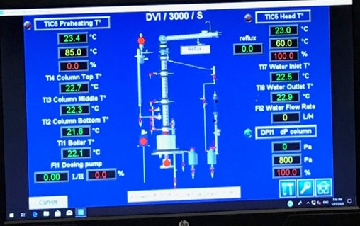
To control the column parameters, use the electronic controllers through the HMI:
- o Dosing pump flow rate controller
- o Differential pressure to control the kettle heating
- o Preheating temperature controller.
- o High temperature detected on the thermostat
- o The liquid level in the kettle or preaheater is not sufficient (level alarm active)
- Liquid level higher than LA1 and LA2
- Dosing pump under voltage
- Vent temperature lower than the high temperature alarm of the thermostat (cut off device) ;
- Cooling water flow rate set on the rotameter using needle valve is higher than the position of Low level switch adjusted on the back of the rotameter (it should be set at least to 100L/h on the back slider)
Controllers
The systems controllers have been configured through the factory. Some parameters remain modifiable by the user, either directly in the controller menu or from the control software.
The controllable parameters are:
- Set points (auto mode)
- Controller output (manual mode)
- Automatic or manual control modes
Control software – AIMS
The software for the DVI/3000 unit has been developed to overview and control the distillation unit from a computer. The remote control gives the following possibilities:
- See indications of all analogical process parameters of the unit
- Enter the control loops set points
- Overview historical data
Powering up the motors, charging and discharging the unit should be done from the electric control box or directly on the unit.
The controlled parameters are the followings:
- Column differential pressures dPIC1.
- Preheating temperature TIC6
- Condenser water flowrate FIC2
- Modifiable parameters are the followings:
- Feeding flow rate by the dosing pump
- Reflux ratio of each column
All other parameters are only indicated and stored in the historical data file.
Using the unit
The general process flow for a continuous feed of the mixture to be distilled to the unit is described below:
- Turn on the Exhaust fan system to the left of the distillation column.
- Fill the feeding storage tank with 15L of the mixture to distill.
- Adjust the feeding flow rate by experimental measurements of volume and time.
- Fill in the kettle with the mixture up to the overflow level.
- Set the reflux conditions turning the three-way switch to the TOTAL REFLUX position.
- Feed the condenser with water circulation of at least 200 L/h.
- Feed with cold water to all the distillate and residue coolers.
- Start heating the kettle until you note some vapours near the column reflux head.
- Wait until the temperature profile along the column is stable.
- Select the level of introduction of the mixture into the distillation column.
- Start the dosing pump, the feeding flow rate should have already been adjusted before starting the distillation process.
- Adjust the preheating temperature according to the level of mixture introduction into the column and the respective temperature.
- Power up the preheater when its level is enough.
- Wait for all temperatures to stabilize.
- Write down all process values and set points.
- Set the reflux ratio to the value you want.
- Wait for all temperatures to stabilize.
- Write down all process values and set points.
- Take samples of the interesting phases, for example feeding mixture, distillate and residue.
- Depending on the experimental procedure, change the distillation parameters, as required (batch distillation with total reflux, continuous distillation with various reflux ratios, feeding level into the distillation column).
Data acquisition
During the experiments, students need to collect the following data in their lab books:
- Temperatures from TI1 to TI8
- Differential pressure drops dPIC1
- Flow rates: cold water in condenser FIC2, column feeding flow rate FI1,
- Constant parameters: Reflux ratio, heating power boiler.
- Samples of the following products: feeding mixture, residues, and distillates for which alcohol concentration will be measured by a specific method.
Experimental Procedure
The video of the experimental procedure is provided in the following link: EXPERIMENT VIDEO.
You will also benefit by visiting the video from the previous distillation experiment that was completed last semester, as that one has a more detailed description of the valves and sensors: Term 1 Experiment Video
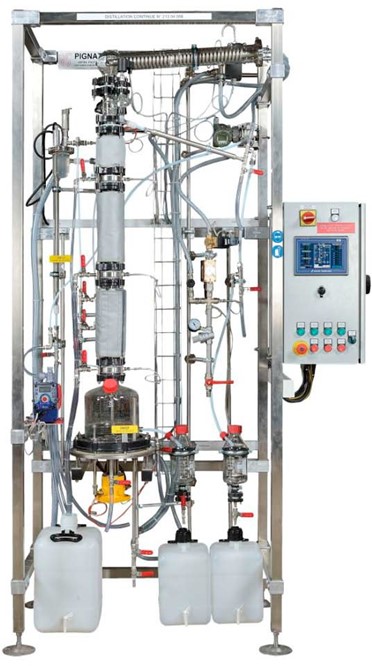
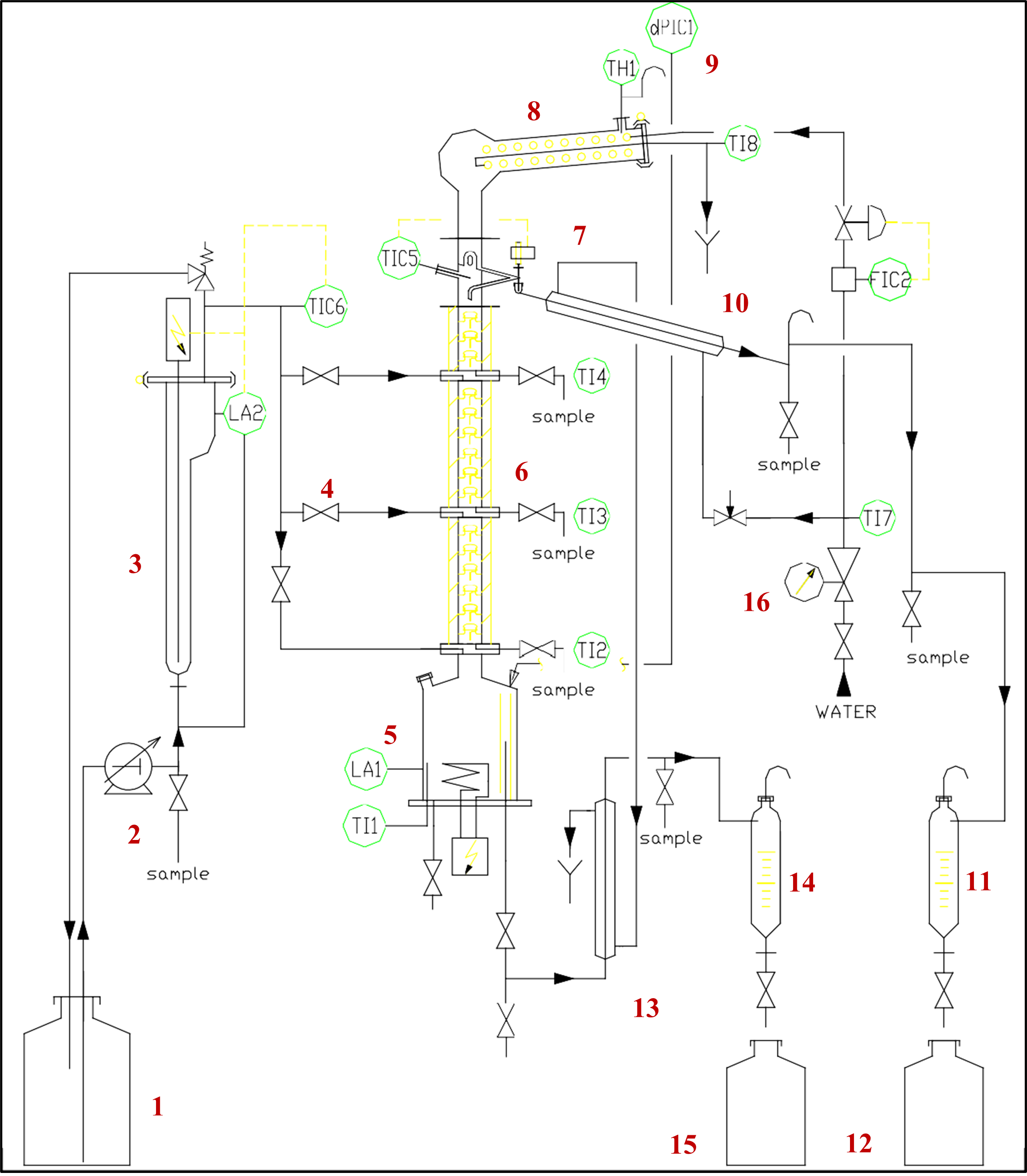
This distillation process will be run on continuous basis using the dosing pump. The mixture of ethanol and water will be fed onto the first (lowest) level in the column by opening valve V4. With continuous feed students will be collecting and analyzing the distillate and residue on continuous basis. Distillate will be captured in the graduated glass receiver (Component 11 in Figure 2) and the residue will be collected in another graduated glass receiver (component 14 in Figure 2). Valves V12 and V15 will have to be opened, to drain the distillate and residue from the graduated cylinders into the storage tanks if the liquid levels in the cylinders will be reaching maximum volume. Two runs will be completed with different reflux ratios, one with the value of 1.0 and the second one with the value of 3.0 and results compared afterwards.
- Turning on the system
- Turn on exhaust fan in the lab (the switch is located on the left hand site to the distillation column on the wall).
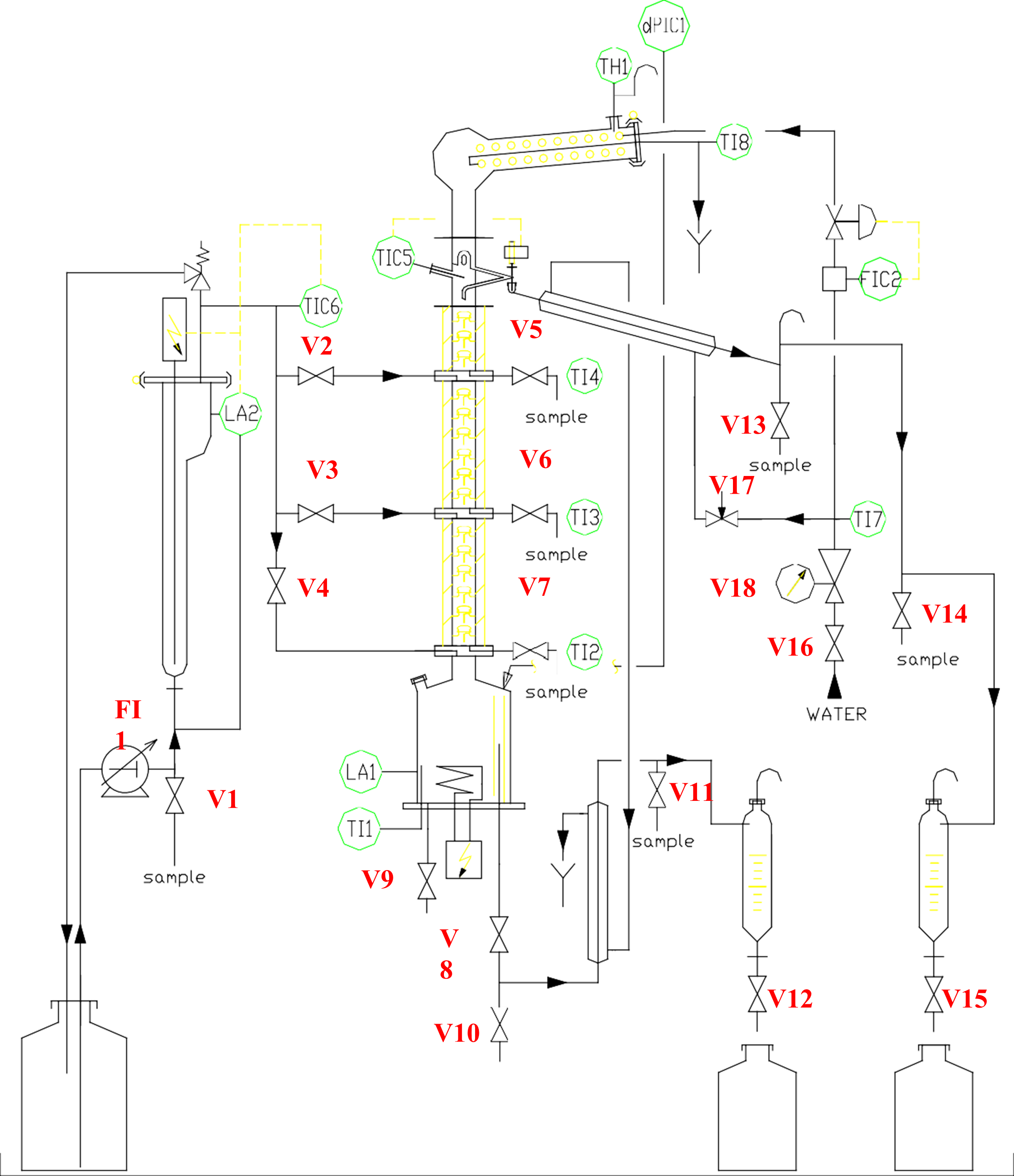
- Turn on the control cabinet.
- Turn on main switch. You should see the white light indicator turned on.
- Push on green button (General power).
- Opening cooling water to condensers(refer to Figures 6 and 7)
Check that the hoses for cooling water are directed to the drain in the laboratory, so that water will drain into the trench. Open the main water supply valve in the lab and then open the feeding valve of the unit V16 to make possible the cold water circulation. Check the water supply pressure on the pressure gauge (the network pressure into the unit circuit should be 2 bars). Check if the limit switch for the minimum water flow rate which is attached to the rotameter is set (you can slide it up or down on the guides behind the rotameter) on the level of 100 L/h. Adjust it if necessary. Adjust the water flow rate with the needle valve V18 to 200 L/h. Ensure that water is indeed draining into the trench.
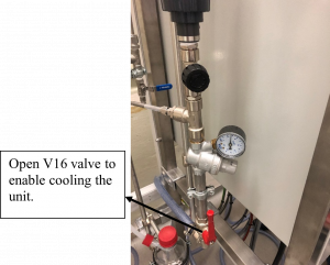
Figure 6: V16 water supply valve
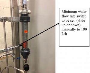
Figure 7: Rotameter with needle valve V18
Warnings:
If the cold water flow rate is too low for the quantity of vapours that reach the condenser and have to be condensed during the experiment, the general vent temperature will increase. The thermostat will then detect a high temperature alarm and stop the dosing pump and the kettle heating.Solution:
Increase the water flow rate to 300 L/h to accelerate the cooling of the general vent thermostat. In case of high temperature alarm on the thermostat, always think about the causes:
Cold water flow rate not adjusted correctly.
The unit has been put under reduced pressure whereas it is not authorized.
Restart the distillation unit.
- Calibrating the dosing pump and charging the unit with ethanol-water mixture
- Before charging the kettle you need to find the maximum flow rate, the pump can produce and generate the calibration graph for the pump
- Place the pump suction flexible hose into the tank containing the mixture to distill.
- To collect the liquid flowing from the valve V1 put the graduated cylinder under the discharge from V1.
- Open the valve V1 and make sure that valves V2, V3, V4 are closed (feed inlets into the column).
- Adjust the pump flow rate by setting the maximum stroke length and 90 % frequency on the pump dials (verify this step with your instructor).
- On the HMI interface select FI1 flow Indicator and in the manual mode put the set point at 100%.
- To prime the pump push on the green button on the control cabinet for the dosing pump and wait for the liquid to flow from V1.
- Once the liquid drains to your cylinder stop the pump by pressing the red push button for the dosing pump on the control cabinet.
- Now you are ready to measure the flow rate of the pump at 100% controller output.
- Replace the graduated cylinder under the valve V1, turn on the pump to collect the liquid in predefined amount of time and stop the pump. Calculate the flow rate of the liquid.
- Repeat the measurement three more times at different settings on the HMI pump controller (e. g. 70%, 50%, 20%), not on the pump directly. This will allow you to generate calibration graph for the pump.
- If the kettle is empty you will have to charge the mixture into the unit using the dosing pump. Before adding the feed mixture, make sure that the kettle temperature is below 30°C. This should be indicated on HMI TI1.
- Check that valves V9 and V10 are closed.
- Open the valve V8.
- Open the valve V4.
- Place the pump suction flexible hose into the tank containing the mixture to distill.
- With the pump controller set to 100% output in manual mode on HMI, turn on the pump by pressing the green push button on the control cabinet for the pump and observe how the liquid is being transferred into the kettle.
- Charge the kettle up to the overflowing level. When you see that the liquid is overflowing to the residue glass receiver (overflow volume of the kettle is 3 Liters), stop the pump and temporarily close the valve V8 to prevent siphoning action. Open the valve V8 after 3-4 minutes.
- Heating the unit
- Heating the ethanol-water mixture can be accomplished in two control modes: manual or automatic. In automatic mode the user enters the differential pressure set point in the controller DPI1 dP in automatic mode. The power output to the heater varies depending on the current pressure differential in the column. In manual mode, the user enters the % of the output on the controller. 100% output will feed 2 kW of power to the heater, while 50% set point will send 1kW power to the heating elements.
- To access the controller, click on DPI1 dP column tab and select automatic mode. Type 1200 kPa as the set point, making sure that Auto mode is selected.
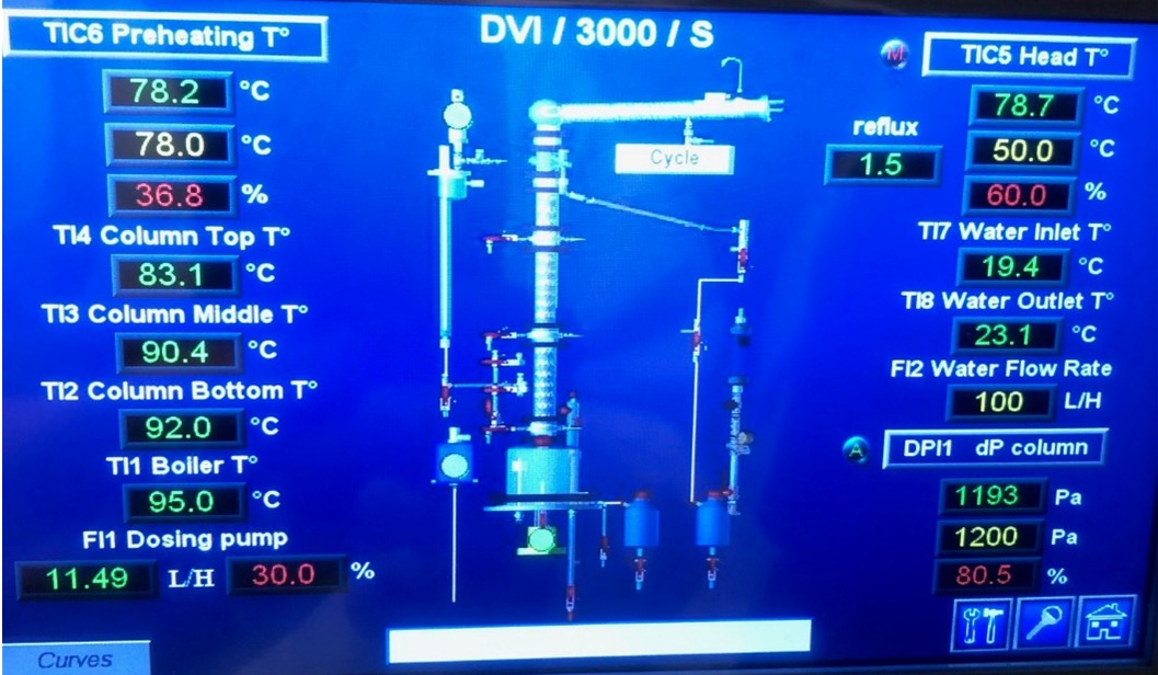 Figure 8: Setting up the heating of the column
- Weigh out the vessel containing your feed to be distilled (required for mass balance calculation). This step will have to be repeated after the distillation process is completed to determine the mass of your feed mixture dispensed.
- Check if the three way switch on the control cabinet is set to REFLUX.
- To start heating, press the heating kettle button on the control cabinet. Wait until you see some vapours near the column reflux head. Wait until the temperature profile along the column is stable.
- If there is excessive flooding on any of the trays. Lower the differential pressure set point on DPI1 dP Column so that there is adequate bubbling at each tray (Do not set it lower than 900 Pa).
- In this run you will be using the lowest level for introducing mixture into the column. Make sure that valves V2 and V3 are closed and open valve V4.For your continuous process the dosing pump should be turned on. The feeding flow rate of the ethanol-water mixture should be between 11.0 and 13.0 L/h. Check the calibration graph you generated in order to determine the proper controller output for your required flow rate. Your settings should be done in manual mode with the set point on FI1 around 20-30%. Verify it with your calibration graph and adjust accordingly.
- Adjust the preheating temperature to 80°C on TIC6 in automatic mode (set point on the controller set to 80°C) and start the dosing pump (push dosing pump green button on control cabinet) to fill preheater reservoir.
- When liquid level in the preheater is reaching the top of the glass cylinder, power up the preheater by pressing the green push button for preheater on the control cabinet. Stop the dosing pump and wait until the temperature in the preheater cylinder will approach the set point of 80°C and then when ready, restart continuous feed into the column.
- At this time set the reflux ratio on the control cabinet using TIC 5 Head controller (go down to point 5 in this manual for instructions).
- Wait for all temperatures to stabilize;
- Write down all process values and set points
- At the end of your experiment – To stop heating at the end of experiment, adjust the set point on the controller dPI1(kettle heating control) and TIC6 (preheater heating control) to 0 on the HMI and press the stop buttons on the control cabinet for preheater and the kettle. In any emergency click the Emergency Kill button on the control cabinet. This will depower the unit.
- Reflux mode setting
Two runs will have to be done, one with Reflux ratio 1.0 and the second run with reflux ratio 3.0
The reflux ratio, R, is defined as:
(1) 
- On the TIC 5 Head T controller on the HMI set the reflux ratio to the value 1.0. This can be done by running the controller in manual mode with settings of 50% on TIC 5_OP. You should see the reflux time 3 seconds and Withdraw Time 3 seconds on the HMI automatically calculated.For the second run you will have to put the reflux ratio equal to 3.0. For these conditions your controller output on TIC 5_OP should be set to 75% in manual mode (Reflux time 4.5 seconds, Withdraw time 1.5 seconds).
- Put the three way switch on the control cabinet from REFLUX to CYCLE and restart the dosing pump.
You should be able to see and hear the solenoid valve on the top of the column opening and closing. When the valve is closed the system is in total reflux position and when it is open, the product-Distillate is being removed from the system. The cycle time is 6 seconds in total and depending on the reflux ratio settings on the TIC5 Head T controller, the valve will be working on and off.
- Sampling of liquids and measurements
- Once the system is in steady state (stable temperatures, continuous feed of the preheated ethanol-water mixture with the flow of the distillate and residue liquid) you are ready to collect samples to measure the ethanol concentration across the column and conduct mass flow rate measurements of the liquid being processed in the column.
- Wear insulating gloves as the samples will be hot.
- Sampling during the experiment is necessary to characterize the column. On the DVI/3000 unit, you can sample the following phases:
- Cooled residue valve V11 (for continuous process only)
- Cooled distillate valve V14.
- Feeding mixture valve V1
- Mixtures into the column valves V5, V6, V7 (HOT!)
- Collect 10 ml sample into the glass container. Cup the container right after collecting the liquids. Once the sample has cooled use digital densitometer and determine the ethanol concentration % on mass basis and report it to your notebook
- Refer to the operating manual for the densitometer or ask your instructor for the directions
- You should have following 6 samples collected:
- V1
- V11
- V5, V6, V7 (hot liquids. )
- V14
- Determine the mass flow rates of feed, distillate and residue by collecting small volumes of the liquids into graduated cylinders within a predefined time interval
- Complete the mass balance for each of your runs (mass of the liquid fed and mass of the distillate and mass of the residual liquid collected in graduated glass receivers)
- Completing the experiment
- Once samples are collected and mass flow rates determined, start cooling the system by adjusting the set points to 0 on the controllers DPI1 dP (kettle heater) and TIC 6 Preheating T
- Stop dosing pump by pressing the red push button on the control cabinet for the pump
- Stop the preheater by pressing the red push button on the control cabinet for the preheater
- Stop kettle heater by pressing the red push button on the control cabinet
- Once the temperature in the column drops to 40°C (at the top of the column on TIC5) stop the cooling water by closing the water valves and shut down the cabinet.
- Turn off the exhaust fan in the laboratory
Report
- Use the pump calibration data to calculate the pump curve (the relationship between controller % setting and pump flow rate). Show the pump calibration graph with the pump curve/trendline on it. Use that trendline to calculate the feed rate to the column at the given controller setting.
- For the second run: plot a graph of temperature vs position of your sample. (check the video in step 4 for some guidance)
- For both runs: calculate the mole fractions of your samples from mass fractions of ethanol from the densitometer measurements.
- On the same graph, plot mole fractions of ethanol vs position of your sample for each run (two lines on the same graph . Comment on the plots. Check the video below for a way to construct that plot.
Mole Fraction Graph VIDEO
- Check the video below of how to construct the McCabe Thiele diagram and calculate the number of theoretical steps for the first run. Use the result of the video to calculate the efficiency of the column for this first run.
McCabe-Thiele Method VIDEO
- For the second run: Construct McCabe-Thiele diagrams for the second finite reflux run and determine the “number of theoretical steps”. Calculate the efficiency of the column for this run.
- Compare the efficiency between the two runs and comment on them.
Useful Definitions and Data

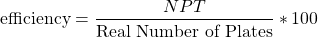
- The column has two parts with 6 perforated plates each and another part with 3 plates which gives 15 real plates.
- The length of the column is 1.0 m
Water/Ethanol liquid vapour equilibrium data (at atmospheric pressure)
| % Mole Ethanol in Liquid | % Mole Ethanol in Vapour | Temperature, °C |
| 0 | 0 | 100 |
| 1.9 | 17 | 95.9 |
| 7.21 | 38.91 | 89 |
| 9.66 | 43.75 | 86.7 |
| 12.38 | 47.04 | 85.3 |
| 16.61 | 50.89 | 84.1 |
| 23.37 | 54.45 | 82.7 |
| 26.08 | 55.8 | 82.3 |
| 32.73 | 58.26 | 81.5 |
| 39.65 | 61.22 | 80.7 |
| 50.79 | 65.64 | 79.8 |
| 51.98 | 65.99 | 79.7 |
| 57.32 | 68.41 | 79.3 |
| 67.63 | 73.85 | 78.74 |
| 74.72 | 78.15 | 78.41 |
| 89.43 | 89.43 | 78.15 |